Ball Screws for Applications in Machine Design where Accuracy Counts
A.MANNESMANN - the technologically leading manufacturer of precision ball screws
Go Directly to All Ball Screw Types from A.MANNESMANN:
Overview of A.MANNESMANN Ball Screws
Ball screws are screw drives that convert a rotating drive motion into a linear motion in normal operation. Due to the favorable friction conditions and the associated very high degree of efficiency (>90%), they are in principle not self-braking so that in reverse operation a linear drive motion can also be implemented in the rotational direction.
Standard Applications with Precision Requirements
The standard applications of ball screws include all the applications that do not need to be assigned to any particular application requirement. The requirements with respect to accuracy, load bearing capacity and dynamics are considerable, but can easily and safely be realized with the precision ball screws of A.MANNESMANN.
DIN-Compliant Positioning and Transport Ball Screws
The standard ball screws from A.MANNESMANN are equipped with double nuts with a side flange. They have preloaded bearing balls in an O-arrangement and can be used both as positioning and as transport ball screws. The nut dimensions and the technical characteristics are based on DIN ISO 3408 or DIN 69051.
Accuracy in All Installation Positions with the Best Values
AM ball screws are produced in the accuracy classes IT 1, IT 3 or IT 5. They are generally equally well-suited for horizontal and vertical operation. The axial force loads of the preloaded ball screws normally bear a maximum of 30% of the dynamic load rating. Usually significantly more than 20,000 hours of operation are reached at a standard travel speed and acceleration.
Advantages at a Glance

Economical advantages
- High long-term durability / service life
- Economical standard designs or custom production
- Excellent energy efficiency
- Maximum long-term precision
- Maximum possible machine availability
- Perfected wear resistance due to nitrided spindle
Technical advantages
- The highest power transmission rates
- Extremely high degree of efficiency (up to 98%)
- Perfect positioning capability and repeatability
- High load capacity
- Exact travel movements
- High rigidity
- Ball screw spindles with ground precision (accuracy IT 1, IT 3, IT 5)
- Constant torque
- Extremely low power losses
- Uniformly low operating temperatures
- Can be used in all installation positions
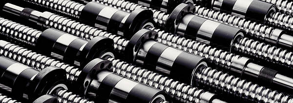
Design of Ball Screws
Ball screws essentially consist of a ballscrew , a ballnut and a large number of balls. The balls make the connection between the ballscrew and the ballnut and are used as a force and movement-transmitting rolling element. The rolling balls roll very precisely in the loaded turns on the ballscrew and in theballnut.
Ball screws are primarily designed for the safe transmission of axial forces. Their force curve occurs via the effective direction of the pressure curves through the balls. With the O-arrangement of the balls, they run with the tip to the outside and with the X-arrangement they run with the tip to the inside. The effective direction of the pressure curves is not only important for the distribution of forces, but also for the generation of the preload.
Dynamics and Precision of Ball Screws
Ball screws together with their support bearing and the drive elements form heavy duty, very dynamic and extremely accurate drive units to, for example, generate advance movements of machine tools. Due to the high load capacity and the tremendous precision, they have proven themselves excellently over decades and are still today a very innovative machine element with a future.
")
Balls and Ball Recirculation Systems
The spatial arrangement of the balls corresponds to that of an endless chain. It therefore not only forms in the loaded turns, but also in the ball return through which the balls must be returned axially to the starting point from the end point of the contact movement between the spindle and the nut. Different basic principles have proven themselves as ball recirculation systems in various design versions (e.g. external and internal return with total, single-run or pipe deflection). Since every ball return has advantages and disadvantages, the correct selection for the application is particularly important in order to achieve the greatest possible realization of the requirements and the best possible functionality.

Two Basic Principles: Driven Nut or Driven Spindle
Ball screws are divided into two basic structural principles after the component that initiates the rotational movement:
Most ball screws are designed with a driven spindle. The rotation of the spindle is then converted into a linear displacement movement of the nut relative to the spindle. This design is also called a normal configuration.
Depending on the task, the design version with a driven nut may be more advantageous under certain circumstances. The rotating drive movement of the nut is converted here into a translatory movement of the spindle relative to the nut. Compared to driven spindles, driven nuts can achieve longer travels, higher rpms and therefore also higher travel speeds. In addition, it is possible to place several nuts on one spindle and to move these individually with separate drives.
In both cases (driven spindles and driven nuts), it is generally structurally possible to linearly move the nut or the spindle.
The design where the spindle as well as the nut are driven is generally also possible and may absolutely be useful under certain circumstances. Regarding the rotational direction of both components, there is then an addition or a subtraction of the individual displacement movements. However, this occurs relatively rarely in practice.
Design of Ball Screws
The structural design of the ball screw is very diverse. It depends on the requirements and in particular on the prevailing installation conditions. Ball screws can be designed with single or double nuts, cylindrically or with flange mounts, with various ball recirculation systems and wipers, single-run or multi-run and with various optional extras. In DIN ISO 3408, the design version is defined with a side flange.
Ball screws may be affected by play in almost all designs or may be preloaded backlash-free. The preload improves the precision, rigidity and the dynamic behavior. The preload therefore also decisively determines the technical usability of the ball screw. Should a transverse force act on the ball screw despite all efforts to avoid this, an increased preload of the nut parts may stabilize the nut system so that this can sufficiently bear the impermissible load on it.
Since the preload is a basic load in the ball screw, which with the external operating load forms the total load that determines the service life, this should not be as high as possible, but rather should always only be chosen to be as high as is necessary.

Ball Raceway Profiles of Ball Screws
The geometry of the ball raceway profiles is not subject to any superordinate specification (standard) and is determined by the manufacturer of ball races and their expertise. That is why ball screws from different manufacturers with the same design and installation size are almost always manufactured with different ball raceway profiles. A spindle-nut combination from different manufacturers is therefore usually not possible and also does not make sense in view of a reliable functionality.
The ball raceway profile greatly affects the load bearing capacity and running quality of ball screws. With precision ball screws, for example as they are used in machine tools, the ogive profile (also called Gothic profile) has developed into a proven standard, since the most important quality-determining variables (such as osculation and pressure angle) are structurally very predictable and controllable.
Hybrid Ball Screws with Ceramic Balls
Another distinction is possible through the power-transmitting balls themselves. Balls made of high-strength hardened steel (100Cr6) are used in most ball screws. They are characterized by a high load capacity and a high wear resistance. In addition, they can be manufactured very precisely and economically.
However, balls made of silicon nitride have also been installed in ball screws for some years now. In these so-called hybrid ball screws, the ceramic balls roll on the steel ball raceways of the spindle and the nut. The ceramic balls are characterized in particular by a high load capacity, low friction and very favorable emergency running properties in the event of a lack of lubricant. However since the load bearing capacity of a ball screw not only depends on the balls, but also on the ball raceways on the spindle and in the nut, a significantly higher load capacity of hybrid ball screws is not necessarily a given. This design without a doubt has advantages at low travel speeds due to the extremely favorable friction conditions.
Different Installation Positions of Ball Screws
The installation position (horizontal or vertical) of a ball screw is generally arbitrary and in principle does not directly affect its function. However, it may affect the load, the lubrication strategy (increased loss of lubricant) and in some cases also the vibration and noise behavior (ball drop in the ball return).
Horizontally installed ball screws, for example, usually travel on a carriage between two points, whereby the carriage mass is accommodated by the guides. Since the travel direction often does not matter and has no preferred direction, horizontally arranged ball screws in the operating state are almost always loaded with virtually equal forces on both sides.
In the event of vertical application, the carriage mass rests on the nut and must be raised or lowered by the ball screw. In this application case, the ball screw is normally loaded on one side with a preferred direction. The load may be reduced through suitable weight-relieving measures, which benefits the durability of the ball screw. However, this requires additional structural machine effort, which is also reflected in the manufacturing costs of the machine.
Most applications of ball screws occur in the horizontal or in the vertical installation position, even though these are only the extreme positions of the generally applicable slanted installation position.
Manufacturing Methods
Various production methods may be used when manufacturing ball screws. Ball screws are therefore available in rolled, twisted, through-hardened or ground designs. Since the manufacturing method directly affects the accuracy and load bearing capacity and therefore ultimately also the usability of a ball screw, it is very important to choose the correct production method.
Thread Grinding, Maximum Precision
Maximum precision is achieved by grinding the ball screw as a final finishing after heat treatment. Ground ball screws are produced at AM in the precision accuracy classes IT 1, IT 3 and IT 5. The average roughness depths of the ball raceway surfaces lie at Rz1 and the arithmetic average roughness value is Ra0.15. Due to the high dimensional accuracy of the nut and spindle, ground ball screws are characterized by a very uniformly smooth and low-vibration running behavior. They have a very long service life and a very high load bearing capacity and long-term accuracy throughout the entire service life.
Grinding is the traditional manufacturing method for the hard machining of ball screws. However, this production chain is also the most cost-intensive due to the large number of individual processing steps and the processing machines required. That is why the optimal utilization and coordination of modern grinding technologies on efficient grinding machines is absolutely necessary for an economic production.
Thread Whirling of the Profile Contour
Normally, ground ball screw spindles are prepared with a grinding allowance in the thread flanks. This preparation is done by whirling the thread before the heat treatment. Whirling is an impact-turning-milling process where the profile contour is machined out of the spindle with a whirling head equipped with cutting inserts. The whirling unit is used in the pitch angle of the ball screw and is moved axially along the spindle at a feed rate corresponding to the desired pitch. The whirling gyroscope rotating around the spindle rod is moved radially out of the axis middle so that it cuts the material with very small chips.
The already good production accuracies can be achieved through the whirling process so that this production method is also suitable for finish machining. This in particular applies when whirling into hard material. However, the process creates surfaces with a high number of facets, which may negatively affect the running quality of the ball screw. Hard whirling is often also called thread peeling.
Materials and Heat Treatment
The selection of materials and the wear-determining heat treatment of ballnuts (through-hardened) and ballscrews (surface-hardened, deep-nitrided) are very important when it comes to economical production with high quality and long durability. A high hardness (67 HRC) of the ball tracks is the basic prerequisite for a long service life of the ball race. It makes the ball screw insensitive to high loads and external influences, such as metal chips.
Areas of Application
The structural design and the manufacturing method of the ball screw are ultimately determined by its use. In addition to "normal" application areas, ball screws can also be used in the high-speed range, in the heavy-load range, in the short-stroke and oscillation range (micro-move) as well as in the smooth running range (e.g. grinding drives). However, ball screws can also be safely used under special ambient conditions, such as under water or in high temperatures. The technological demands and the set expectations are very dependent on the application in the individual application areas. They are very specific and even contrary sometimes. A ball screw that can bear a very high load, for example, will never also have to realize very high travel speeds. In contrast, a highly dynamic ball screw is loaded with comparatively low forces. If a large mass is to be moved in small steps, then usually no high dynamics are also required, but rather a low breakaway torque and a very low friction are expected. That is why special structural designs are necessary that correspond to the respective application profile as precisely as possible.
Ball Screw Types P and T for Positioning and Transport According to DIN ISO 3408
Another distinction among ball screws is the usage purpose, whereby a distinction is made between positioning and transport ball screws according to DIN ISO 3408.
Positioning ball screws (type P according to DIN ISO 3408-1) are backlash-free preloaded systems that are normally used for positioning tasks or in applications with increased requirements (e.g. machine tools). The ball screw ground to very tight dimensional tolerances allows for the indirect measurement of the path from the rotational angle and the thread pitch. The travel accuracy is determined by the path deviation of the ball screw.
Transport ball screws (type T according to DIN ISO 3408-1) are used to move components. Typical applications include handling axes, for example. The spindle thread is not always necessarily ground, but rather is often rolled or whirled. The accuracy requirement of a transport ball screw is much lower than that of a positioning ball screw. However, if a parallel arranged linear measurement system is used to determine the position of the axis for transport ball screws, then the positioning accuracy will no longer be determined by the ball screw, but rather by the resolution and thus by the accuracy of the path measurement system. Better positioning accuracies can be achieved here with transport ball screws than with positioning ball screws. In these applications, the ball screw spindles are usually also ground due to the improved durability and required running quality.
Multi-Spindle Application
Ball screws can also be used as multi-spindle systems, whereby the power transmission and the movement implementation are not realized by one ball screw, but rather are realized by several (usually two) parallel arranged systems. The control system manufacturer offers special operating modes (e.g. master-slave operation or gantry operation) with a very high level of uniformity for this very demanding control technology drive task. The pitch deviations of the parallel arranged ball screw spindles with each other should be as small as possible so that there is no bending out of line or tilting in the movement guides. The control quality of the synchronous travel movements of both spindles in all movement phases is also very important. The force distribution of the load is also very important, since for example in the event of a temporally changing moving load this does not always affect the same parts on the individual ball screws, but rather there may be considerable differences. Since the movement behavior and the force distribution cannot always be predicted, there may be very high additional loads on each ball screw.
")